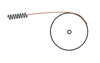
For university we've got to build a small vehicle powered by two tension springs. Since a wheel and these springs have different motions; conversion from a linear to rotary motion is done by attaching a belt to a wheel and the spring in order for all the spring forces to be converted into tangential forces as pictured in the attached image.
The force from the spring can be described as: F = c * u
where F = force [N], c = spring constant [N/mm], u = extension spring [mm]. The maximum extension of the spring is 118 mm and the spring constant is 0.4 N/mm.
The torque as reaction of the spring can be described as: T = F * r
where T = Torque [Nmm], F = force [N] and r = radius of the wheel [mm]
Substitution gives:
T = (c * u) * r
Considering we want a constant torque (500 Nmm) and the force is dependent on the length of the spring; only the radius is variable we get the following:
r = T / (c * u) -> r(0 < u < 118) = 500 / (0.4 * u)
Ofcourse this is a reciprocal function with an asymptote where u = 0.
Since the maximum arc length of the spiral equals the maximum spring length, I thought I could get a variable angle (theta) with the circle circumference equation:
c = r * theta
where c = circumference [mm], r = radius of the wheel [mm] and theta = angle [rad]. c = 118 and r is known from the last equations. substitution gives:
theta (0 < u < 118) = 118 * (0.4*u/500)
Eventually the parametric equation for a circle is:
F (theta) = (x(theta), y(theta))
x (theta) = r * cos (theta)
y (theta) = r * sin (theta)
substituting the previous values gives:
F (0 < u < 118)= (x(u), y(u))
x (u) = (500/(0.4*u)) * cos (118*(0.4*u/500))
x (u) = (500/(0.4*u)) * sin (118*(0.4*u/500))
However my results may look correct (at least its a spiral starting at a radius of around 10) the increasing radius and the arc length (I'm checking my arc length with SolidWorks evaluation tools) are not.
What am I doing wrong? Is there a better way?

